Iranian Classification Society Rules

< Previous | Contents | Next >
1. External dimensions and ratings
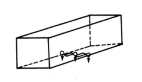
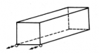
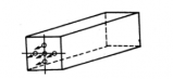
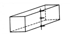
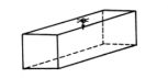
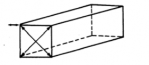
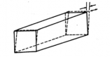
(1) External dimensions and their permissible tolerances as well as the rating of the container or each designation are shown in Table 2.2 and Fig 2.5.
(2) No part of the container is to project beyond the overall external dimensions.
2. Internal dimensions
(1) Closed, vented containers width and height given in
are to comply with the requirements for minimum internal length,
Table 2.3. However, where a top corner fitting projects into the in-
ternal space, that part of corner fitting projecting into the container is not to be considered as
reducing the size of the container.
(2) Containers having partial openings in the sides, are to comply with the requirements for mini- mum internal length and height given in Table 2.3.
(3) Containers having an opening roof, are to comply with the requirements for minimum internal
length and width given in Table 2.3.
(4) Containers having openings in the sides and/or roof, are to comply with the requirements for minimum internal length given in Table 2.3.
![]()
Table 2.2 External Dimensions, Permissible Tolerances and Ratings of containers
![]()
Ch 2
Designation | Height (m m ) H | Width (m m ) W | Length (m m ) L | K1 (m m) Max. | K2 (m m) Max. | Rating R (kg) | |||
Dimension | Tolerance | Dimension | Tolerance | Dimension | Tolerance | ||||
1EEE | 2896 | 0 -5 | 2438 | 0 -5 | 13716 | 0 -10 | 19 | 10 | 30480 |
1EE | 2591 | 0 -5 | |||||||
1AAA | 2896 | 0 -5 | 12192 | 0 -10 | 19 | 10 | 30480 | ||
1AA | 2591 | 0 -5 | |||||||
1A | 2438 | 0 -5 | |||||||
1AX | 〈2438 | 0 -5 | |||||||
1BBB | 2896 | 0 -5 | 9125 | 0 -10 | 16 | 10 | 30480 | ||
1BB | 2591 | 0 -5 | |||||||
1B | 2438 | 0 -5 | |||||||
1BX | 〈2438 | 0 -5 | |||||||
1CC | 2591 | 0 -5 | 6058 | 0 -6 | 13 | 10 | 30480 | ||
1C | 2438 | 0 -5 | |||||||
1CX | 〈2438 | 0 -5 | |||||||
1D | 2438 | 0 -5 | 2991 | 0 -6 | 10 | 10 | 10160 | ||
1DX | ≤2438 | 0 -5 | |||||||
NOTES : (1) All dimensions in table apply when measured at the temperature of 20 ℃. Measurement taken at other tem- peratures is to be adjusted accordingly. (3) The values of and are given in Fig 2.5. | |||||||||
![]()
Ch 2

Fig 2.5 Dimensions and Permissible Tolerances
Table 2.3 Minimum Internal Dimensions and Door Opening's Dimensions of Containers
Designation | Internal Height (m m ) | Internal Width (m m ) | Internal Length (m m ) | Door Opening | |
Width (m m) | Height (m m) | ||||
1EEE | 2655 | 2330 | 13542 | 2286 | 2566 |
1EE | 2350 | 2261 | |||
1AAA | 2655 | 11998 | 2566 | ||
1AA | 2350 | 2261 | |||
1A | 2197 | 2134 | |||
1BBB | 2655 | 8931 | 2566 | ||
1BB | 2350 | 2261 | |||
1B | 2197 | 2134 | |||
1CC | 2350 | 5867 | 2261 | ||
1C | 2197 | 2134 | |||
1D | 2197 | 2802 | 2134 | ||
604. Design Conditions
1. Design load
Containers are to be required to have ample strength to bear the load or force specified in Table
2.4 and not to generate permanent deformation or abnormality which will render it unsuitable for
use. Each structural member of the container is to be so designed as to be capable of withstanding the following conditions.
(1) Stacking: Superimposed mass 213,360 kg.
(2) Lifting: vertical lifting from all four top corners, and lifting from all four bottom corners by means of suitable slings.
(3) Transportation: Restraint and lashing in transit under dynamic loading resulting from road or railway operations or the ship motions.
![]()
(4) Loading and unloading: Concentrated loading due to the cargo handling apparatus, etc. during loading and unloading operation.
![]()
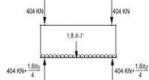
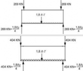
Table 2.4 Loads and forces to be applied
![]()
Ch 2
Item | Where Applied | Direction | Notes |
Stacking | Top corner fittings Off-set : - 38 m m longitudinally - 25.4 m m laterally | Vertically downwards All containers other than 1 D /1DX con- tainers
Applicable to 1EE and 1EEE containers only (a) (b) (c) 1 D /1D X Containers
| Concentrated eccentrically applied load 3,767 kN (942 kN per top corner fitting) Stacking at 40' position and supported in 40' po- sition(404 kN per top cor- ner fitting) Stacking at 40' position and supported in 45' po- sition(269 kN per top cor- ner fitting) Stacking at 45' position and supported in 40' po- sition(404 kN per top cor- ner fitting) 896 kN (224 kN per top corner fitting) |
Top Lifting | Top corner fittings | Vertically upwards for all containers oth- er than 1 D /1DX containers
Applicable to 1EE and 1EEE containers only
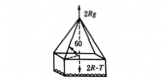
60° to the horizontal for 1 D /1DX con- tainers
| 2 R The lifting forces shall be applied additionally from the 40' position |
Ch 2
![]()
![]()
Table 2.4 Loads and forces to be applied (continued)
Item | Where Applied | Direction | Notes |
Bottom Lifting | Bottom corner fittings (spacing between the line of action of the lifting force and the other face of the corner fitting is not fur- ther than 38 m m) | : Angle to the horizontal
Applicable to 1EE and 1EEE containers only
The is to apply the requirements of the bottom lifting in Table 2.5 in ac- cordance with kinds and designation of containers | 2 R The lifting forces shall be applied additionally from the 40' position |
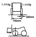
Floor Strength | Floor | Vertically downwards
| per an axle: 7,260 kg per a wheel: 3,630 kg wheel width: 180 m m contact area per a wheel: 142 cm2 wheel centers: 760 m m |
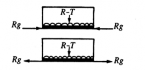
Longitudinal Restraint | Bottom corner fittings | Longitudinal
Applicable to 1EE and 1EEE containers only (a)
(b)
| Concentrated force 2 R (2 R /2 per one side) |
End Wall | End wall | Outerwards normal to the end
| 0.4 Pg |
Side Wall | Side Wall | Outerwards normal to the end
| 0.6 P g |
![]()
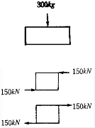
Table 2.4 Loads and forces to be applied (continued)
![]()
Ch 2
Item | Where Applied | Direction | Notes |
Roof Panel | Roof panel (An area of 600 m m × 300 m m located at the weakest area) | Downwards normal to the roof | 300 kg |
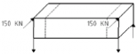
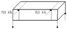
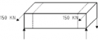
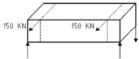
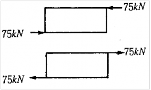
Transverse Racking (All containers other than 1D /1DX containers) | Top corner fittings | Transverse Applicable to 1EE and 1EEE containers only
| Concentrated force 150 kN per top corner fitting (a) Pushing at 45' posi- tion and supported in 45' position (b) Pushing at 40' posi- tion and supported in 40' position (c) Pushing at 45' posi- tion and supported in 40' position (d) Pushing at 40' posi- tion and supported in 45' position (e) Pulling at 45' position and supported in 45' position (f) Pulling at 40' position and supported in 40' position (g) Pulling at 45' position and supported in 40' position (h) Pulling at 40' position and supported in 45' position |
Ch 2
![]()
![]()
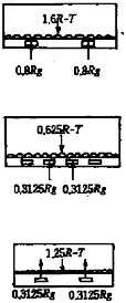
Table 2.4 Loads and forces to be applied (continued)
Item | Where Applied | Direction | Notes |
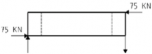
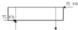
Longitudinal Racking (All containers other than 1 D/1D X contain- ers) | Top corner fittings | Longitudinal
Applicable to 1EE and 1EEE containers only
| Concentrated force 75 kN per top corner fit- ting (a) Compression at 45' position and supported in 45' position (b) Compression at 45' position and supported in 40' position (c) Tension at 45' posi- tion and supported in 45' position (d) Tension at 45' posi- tion and supported in 40' position |
Fork-lift pocket (where fork-lift pocket is fitted as 1CC, 1C, 1CX and 1 D X containers) | Fork-lift pocket (Width 200 m m , the part form side to 1,828 ± 3 mm) | Vertically upwards | Distributed load 0.8 R per fork-lift pocket |
Fork-lift pocket (where fork-lift pocket is fitted for empty as 1CC, 1C and 1CX containers) | Fork-lift pocket | Vertically upwards | Distributed load 0.3125 R per fork-lift pocket |
Grappler arm | Grappler lifting position | Vertically upwards | Distributed load 1.25 R /4 per grappler lift- ing position |
Ch 2
![]()
2. Corner fittings
(1) All containers shall be equipped with corner fittings at the top and bottom corner, the di- mensions of which are given in Figs 2.6 and 2.7. 1EEE and 1EE units shall also have fittings in 40' position, as shown in Fig 2.8, the dimensions of which are given in Figs 2.9 and 2.10.

![]()
Fig 2.6 Top Corner Fitting (Dimensions : mm)
Ch 2
![]()
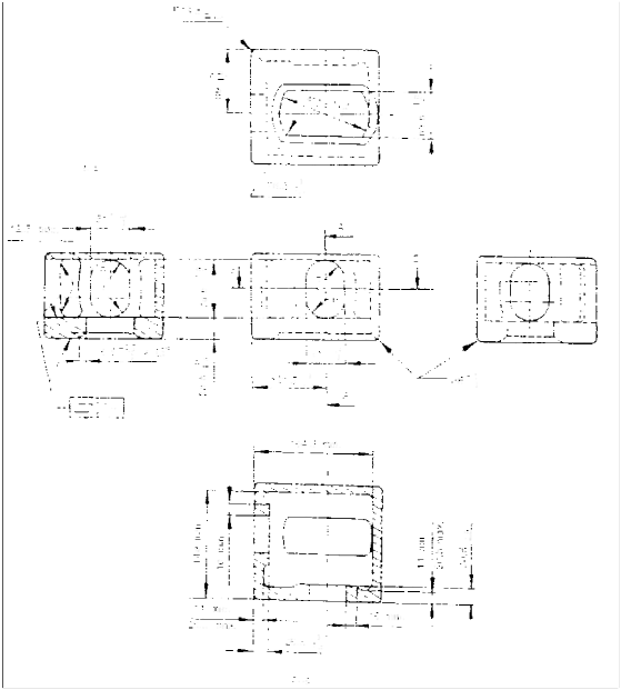
NOTE:
(1) Solid and broken lines (― and ----) show surfaces and contours which are to be physically duplicated in
the fitting.
(2) Phantom lines (―--―) show optional walls, which may be used to develop a box shaped fitting.
(3) Scantlings indicated by * are not to be more than the thickness of the adjacent part surrounding a hole at the side or end.
(4) Notes (1) to (3) above are to also be applied to the Fig 2.6.
Fig 2.7 Bottom Corner Fitting (Dimensions : mm)
Fig 2.8 45 foot container with corner and intermediate fittings
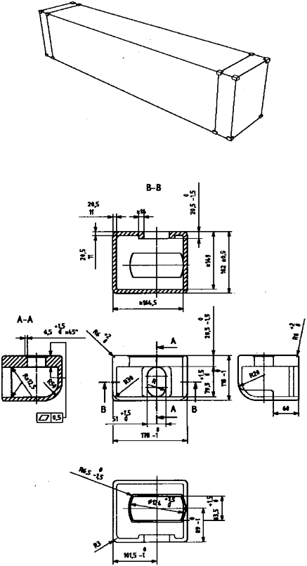
Fig 2.9 Top intermediate fitting (Dimensions : mm)
![]()
Ch 2
![]()
Ch 2
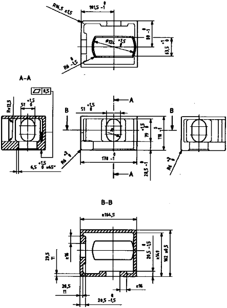
Fig 2.10 Bottom intermediate fitting (Dimensions : mm)
(2) Where dimensions are not specified for inner and outer edges of apertures, these edges are to be given a radius of 3 mm.
(3) Wthrhouergeh c2o.1r0nearsfipthtianngtoomr ilninteerm(―ed-i-a―te) faitntdingis hmasadaentoptthioenmalininimneurmsidiemwenaslliosnhoowf n14i9n mFimgs, t2h.6e junction of the mandatory horizontal face to the optional inner side wall may be provided with a radius not exceeding 5.5 mm. If a greater radius is required, the 149 mm dimensions are to be increased accordingly.
(4) The upper faces of the top corner fittings are to protrude above the top of the container by a
minimum of 6 mm.
Ch 2
![]()
3. Base structure
(1) All containers are to be capable of being supported by their bottom corner fittings only.
(2) The lower faces of the load transfer areas including those of the end transverse members, are to be one plane located 12.5 mm above the plane of the bottom faces of the lower corner fit- tings of the containers.
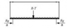
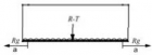
(3) Containers are to be designed so that no part of the base structures is to deflect more than 6 mm below the bottom faces of the bottom corner fittings under a uniformly distributed load equal to 1.8 R-T.
(4) The base structures of the containers are not to protrude below the corner fittings under a uni- formly distributed load equal to the maximum payload.
(5) All containers, other than 1 D, are to have end transverse member and sufficient intermediate load transfer areas of sufficient strength to permit vertical load transfer to or from the longi-
tudinal members are assumed to lie within the two 375 mm wide zone defined by the broken lines in Fig 2.11 with longitudinal dimension over 25 mm. Container are to also be capable of being supported on load transfer areas only in their base structure.
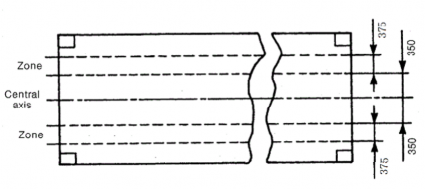
Fig 2.11 Load Transfer Areas in Base Structures (Dimensions : mm)
(6) Containers other than 1 D, having all their intermediate transverse members spaced at 1000 mm apart or less are given in Fig 2.12 through 2.16. The maximum load to be transferred at the load transfer zone is not to exceed 2 R.
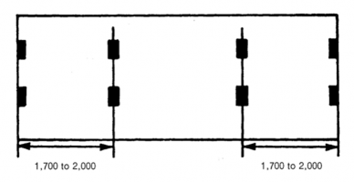
Fig 2.12 Load transfer Areas in Base Structure for ICC, 1C or 1CX Containers (Dimensions : mm)
![]()
Ch 2
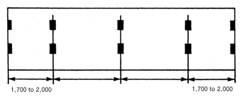
Fig 2.13 Load transfer Area in Base Structure for 1BBB, 1BB, 1B or 1BX Containers (Dimensions : mm)
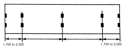
Fig 2.14 Load transfer Area in Base Structure for 1AA, 1A or 1AX Containers without Gooseneck Tunnel (Dimensions : mm)
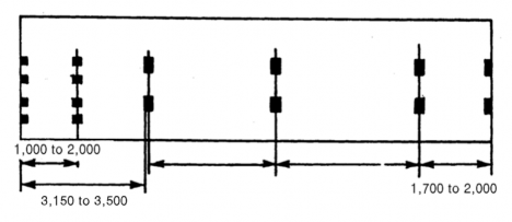
Fig 2.15 Load transfer Area in Base Structure for IAAA, 1AA, 1A or 1AX Containers with Gooseneck Tunnel (Dimensions : mm)
Ch 2
![]()
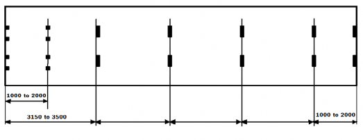
Fig 2.16 Load transfer Area in Base Structure for 1EEE,1EE, 1AAA, 1AA, 1A or 1AX Containers with Gooseneck Tunnel-Requirements if 7pairs of load transfer areas are to be fitted (Dimensions : mm)
Ch 2
![]()
4. End structure
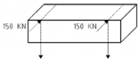
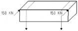
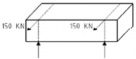
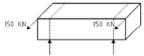
For all containers other than 1 D and 1 DX, the side way deflection of the top of container with respect to the bottom of the container at that time when it is under transverse racking force of 150 kN is not to cause the sum of the changes in length of the two diagonals in each end wall to ex- ceed 60 mm.
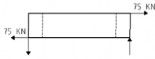
5. Side structure
For all containers other than 1 D, the longitudinal deflection of the top of the container with re- spect to the bottom of the container at the time when it is under longitudinal racking force of 75 kN is not to exceed 25 mm.
6. Door openings
(1) All door openings are to be as large as possible, minimum dimensions of door openings are given in Table 2.3.
(2) Doors are to be equipped with securing devices which is capable of being sealed up.
(3) All doors are to be capable of being clasped properly when opened.
7. Fork-lift pockets
(1) Containers 1 CC, 1 C, 1 CX 1 D and 1 DX may be provided with fork-lift pocket, and fork-lift pocket may be provided on containers 1 CC, 1 C and 1 CX for empty handling only.
(2) The positions, dimensions and allowable tolerances of fork-lift pocket are to be in accordance
with Fig 2.17, and are to pass completely through the base structure of the container.
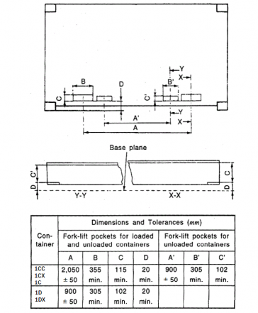
Fig 2.17 Positions, Dimensions and Tolerances of Forklift Pocket
Ch 2
![]()
8. Gooseneck tunnels
(1) Containers 1EEE, 1EE, 1AAA, 1AA 1A and 1AX may be provided gooseneck tunnels. In this
case, dimensions and allowable tolerances of gooseneck tunnels are to be in accordance
Fig 2.18.
with
(2) Load transfer
Fig 2.19.
area is to be designed in base structure of gooseneck tunnels in accordance with

Fig 2.18 Positions, Dimensions, Tolerances of Gooseneck Tunnels
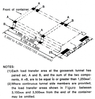
Fig 2.19 Load Transfer Area in the Base Structure of the Gooseneck Tunnel
Ch 2
![]()
9. Grappler arms
(1) Containers may be provided with the features for handling at the base by means of grappler arms or similar devices. The dimensional requirements are specified in Fig 2.20.
(2) Grappler arm contact area to be flat, and level with corner and lip clean and square.
(3) Where stops are provided at ends of pockets they are to be sloped as indicated in Fig 2.20.
(4) External wall of grappler arm including rivet or bolt heads is not to be more than 12 mm from the inside of the lip.
Fig 2.20 Dimensions of Grappler Arm Lifting Areas
605. Type Approval Inspection
1. General
(1) The items of type approval test are to comply with the followings:
(a) Visual inspection
(b) Dimensional inspection
(c) Mass measurement
(d) Strength tests
(e) Weathertightness test
(2) Measuring instruments to be used for the test and inspection of the calibrated.
container are to be duly
(3) Alternative test procedures to those specified in preceding (1) will be accepted be equivalent by the Society.
if considered to
(4) Test procedures for specific purpose container may be properly modified and omitted.
2. Visual inspection
(1) Visual inspection is to be carried out at a proper stage and period during production and/or af- ter completion in order to ascertain that the constructions, materials and workmanship of the container are in compliance with the requirements of this Section without any visual defects in each component of the container.
(2) In the visual inspection, it is to be ascertained that the door can be smoothly operated and secured.
Ch 2
![]()
3. Dimensional inspection
Dimensional inspection is to be carried out after the completion of all the works in order to ascer- tain that the container meets the dimensional requirements of this Section
4. Mass measurement
Mass measurement is to be carried out after the completion of all the works in order to determine the tare mass of the container.
5. Strength tests
(1) Strength tests are to be carried out as specified in Table 2.5 after the completion of all the works.
(2) In the strength tests, measurements are to be taken as required in Table 2.5. Additional meas-
urements may be required, where deemed necessary by the Society.
(3) During the strength tests, deformations which generated on each part of container based on their designation are not to be over the requirements specified in 604. On completion of the tests, the container is to show neither permanent deformation nor abnormality which will render it un-
suitable for use.
Ch 2
![]()
![]()
Table 2.5 Test Procedures and Measurements of Type Approval
Item | Procedures and Measurements |
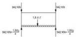
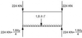
Stacking | Procedure: Internal load: 1.8 R-T uniformly distributed over the base. (1) Applied forces: With the container in the normal position supported at the base corner fittings, compressive forces equivalent to 942 kN are to be applied to each corner post through rigidly held dummy corner fittings arranged to simulate an overstowed con- tainer base. The test is to be repeated to cover for all positions of offset namely 38 mm longitudinally and 25.4 mm laterally. (2) For 1EEE and 1EE containers, the stacking forces shall be applied vertically from the 1EEE/1EE position and separately from the 1AAA/1AA/1A position according to the requirements specified in Table 2.4, stacking test (a), (b) and (c). (3) For a 1D/1DX container, compressive forces equivalent to 224 kN are to be applied to each corner post.
Measurement: (1) Deflections at lowest point of both side rails and at the longitudinal centre line of the base which may be taken before the application of axial loads. (2) Deflections in two directions at midheight, or other point of maximum deflection of the corner posts, and permanent set remaining on removal of the load. |
Top Lifting | Procedure: Internal load : 2 R-T uniformly distributed over the base. (1) Applied forces: With the container in the normal position, lifting forces are to be ap- plied gradually to the top corner fittings, vertically to containers other than 1D /1D X container (2) For 1EEE and 1EE containers, the lifting forces shall be applied vertically from the 1EEE/1EE position and separately from the 1AAA/1AA/1A position (3) at 30° to the vertical in the case of 1D /1DX containers. (4) The container shall be supported for 5 min. and then lowered to the ground.
Measurements: (1) While loaded and supported by the four bottom corner fittings before lifting clear, the deflection at lowest points of both side rails and at the longitudinal centre line of the base. (2) Permanent set remaining on removal of the load |
![]()
Designation | Angle |
1EEE, 1EE 1AAA, 1AA, 1A | 30° |
1BBB, 1BB, 1B, 1BX | 37° |
1CC, 1C, 1CX | 45° |
1 D, 1DX | 60° |
Table 2.5 Test Procedures and Measurements of Type Approval (continued)
![]()
Ch 2
Item | Procedures and Measurements |
Bottom Lifting | Procedure: Internal load: 2 R-T uniformly distributed over the base. (1) Applied forces: With the container in the normal position, lifting forces are to be ap- plied gradually through the bottom corner fitting side aperatures as follows: (2) For 1EEE and 1EE containers, the lifting forces shall be applied from the 1EEE/1EE position and separately from the 1AAA/1AA/1A position (3) In each case, the line of action of the lifting force and the outer face of the corner fitting or intermediate fitting shall be no farther apart than 38mm. The container shall be supported for 5 min. and then lowered to the ground. Measurements: Same as measurements of the top lifting |
Floor Strength | Procedure: Internal load: Nil. Applied forces: With the container supported at the bottom corner fittings, a vehicle equipped with 180 m m wide tyres at 760 m m centres each having a contact area of 142 ㎠ loaded to an axle mass of 7,260 kg is to be maneuvered over the entire floor area.
Measurements: Deflection of the base. |
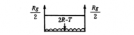
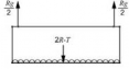
Longitudinal Restraint | Procedure: Internal load: R-T uniformly distributed over the base. Applied forces: With the container in the normal position, anchored by locking devices through the bottom apertures in the bottom corner fittings at one end, forces equiv- alent to Rg are to be applied to each side rail through the bottom apertures in the bottom corner fittings at the other end first in compression then in tension. For 1EEE and 1EE containers, the forces shall be applied from the 1AAA/1AA/1A position
Measurements: The change in length of both bottom side rails during and after the test (in each direction) |
End Wall | Procedure: Internal loading and application: 0.4 Pg uniformly distributed over the wall under test in such a way as to allow free deflection of the end wall.
Measurements: Deflection and permanent set at the centre and at least two other locations. |
Ch 2
![]()
![]()
Table 2.5 Test Procedures and Measurements of Type Approval (continued)
Item | Procedures and Measurements |
Side Wall | Procedure: Internal loading and application: 0.6 Pg uniformly distributed over the wall under test in such a way as to allow free deflection of the side wall and its top and bottom side rails. Each side is to be tested separately but only one side need to be tested when both are similar in construction.
Measurements: Deflection and permanent set at the centre of side wall and the centre of the top and bottom side rails. |
Roof Panel | Procedure: Internal load: Nil. Applied load: 300 kg uniformly distributed over a 600 m m × 300 m m area at the weakest section of the roof.
Measurements: Maximum deflection and permanent set of section under test. |
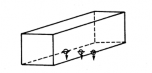
Transverse Racking | Procedure Internal load: Nil. Applied forces: The test is to be carried out to all containers other than 1D /1D X containers. With the container in the normal position anchored by locking devices through the apertures in the bottom corner fittings, transverse racking forces of 150 kN are to be applied separately or simultaneously to each top corner fitting on one side. Lateral restraint is to be taken up by the anchor devices diagonally opposite to the applied forces. The force(s) is to be applied first towards then away from the container. For 1EEE and 1EE containers, the forces shall be applied according to the requirements specified in Table 2.4, transverse racking test (a) through (h).
Measurements: Difference in diagonals before, during and after testing. |
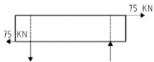
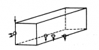
Longitudinal Racking | Procedure: Internal load: Nil. Applied forces: The test is to be carried out to all containers other than 1D /1D X containers. With the container in the normal position anchored by locking devices through the apertures in the bottom corner fittings, longitudinal racking forces 75 kN are to be applied separately or simultaneously to each top corner fitting on one end. Longitudinal restraint is to be taken up by the anchor devices diagonally opposite to the applied forces. The force(s) is to be applied first towards then away form the container. For 1EEE and 1EE containers, the forces shall be applied according to the requirements specified in Table 2.4, longitudinal racking test (a) through (d).
Measurements: Longitudinal displacement of top side rails. |
Table 2.5 Test Procedures and Measurements of Type Approval (continued)
![]()
Ch 2
Item | Procedures and Measurements | |
Fork-lift pocket | Procedure: Internal load: 1.6 R-T (for empty container, 0.625 R-T ) uniformly distributed over the base. Applied forces: The tset is to be carried out to 1CC, 1C, 1CX, 1D and 1DX containers where fork-lift pocket is fitted. The container is to be supported for 5 minutes by two bars 200 m m wide inserted in the fork pockets to a depth of 1,828 ±3 m m Measurements: Undue local distortion during the test and any permanent distortion on removal of the load. | |
Grappler arm | Procedure: Internal load:1.25 R-T uniformly distributed over the base. Applied forces: The test is to be carried out to containers where grappler arm is fitted. The container is to be supported for 5 minutes by pads at the four grappler arms intended to be used. Measurements: Undue local distortion during the test and any permanent distortion. | |
Weathertightness | Procedure: All surfaces of the container are to a water test from a 12.5 m m nozzle, with a water pressure of 1 bar at the nozzle, second at a distance of 1.5 m from the sur- face under test. Observation: The interior of the container is to remain dry. | |
One door off Operation | Stacking | Procedure: Refer to Stacking of this Table. The loads are applied to design condition of manufacturers. Measurements: Refer to Stacking of this Table. |
Transverse Racking | Procedure: Refer to Transverse Racking of this Table. The loads are applied to design condition of manufacturers. Measurements: Refer to Transverse Racking of this Table. | |
6. Weathertightness test
Weathertightness test is to be carried out as specified in
Table 2.5 after all strength tests have
been completed or at a reasonable stage during production. On completion of the test, the container is to be free from penetration of water.
606. Production Unit Inspection for Type-Series Containers
The kinds of tests and inspections for production unit inspections of type-series containers are to be
![]()
in accordance with the requirements in requirements of 605. of this Section.
Ch 2, 403. and to be carried out in accordance with the
![]()
Ch 2